35th Avenue Storm Drain Investigation
Uncovering an unknown underground asset through confined space manned entry.
Written by: Arno Leskinen, PE | Susanna Mabery
Introduction
Understanding the location of underground utilities is an important pre-design step prior to excavation during construction. While obtaining accurate information on utilities through as-builts can save both time and money during construction, accurate data is not always available, which poses significant risks to the project.
The City of Phoenix (City) is implementing a series of major infrastructure improvements located in Pressure Zones 3D and 4A to move water from the Salt River Project (SRP) system northward to the Central Arizona Project (CAP) service area. These improvements will help to reliably deliver water to the northern parts of the City during periods of drought and during times when the availability of CAP water is reduced. Dibble designed these improvements, which include replacing approximately 2.5 miles of an existing 36-inch water transmission main (WTM) with a new 42-inch WTM along 35th Avenue from Thunderbird Road to Grovers Avenue. The new WTM will provide increased capacity and eliminate flow restrictions caused by the existing 36-inch WTM.
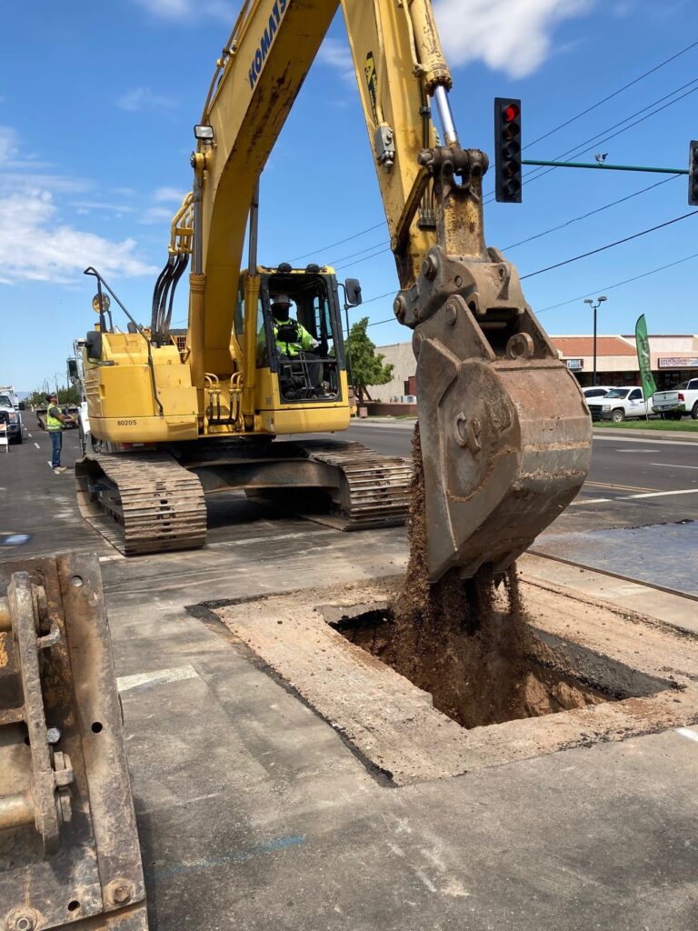
During the utility evaluation for the alignment selection of the new pipeline, Dibble discovered that the preferred alignment would be in close proximity to a large-diameter storm drain for approximately one mile, between Acoma Drive and Paradise Lane. Dibble and the City searched for as-built documentation of the storm drain but were unable to locate as-builts for the one-mile segment in question. Secondary sources indicated that the storm drain did not follow standard design practice and had multiple directional changes along the one-mile alignment. To minimize risk during construction, Dibble needed the dimensions and alignment of this storm drain to accurately detail the infrastructure on the construction documents.
Dibble explored several options – ground penetrating radar (GPR), sonde float balls, and 3D scanning – to determine the dimensions and alignment of the underground storm drain. Since none of these methods were ideal for the 2.5-mile section, Dibble proposed a manned entry field survey as the best solution to document the storm drain.
Method
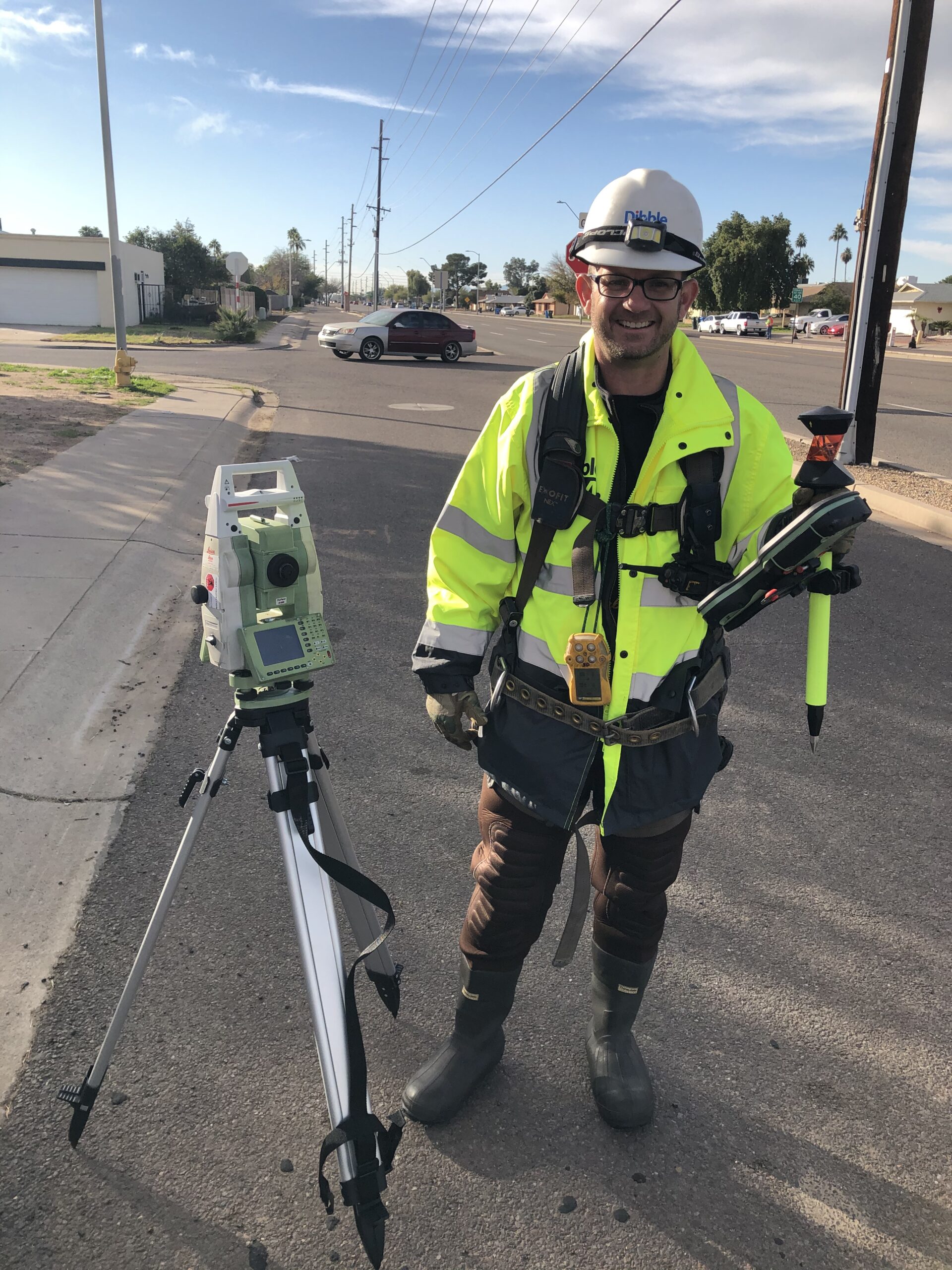
Dibble’s survey team determined the horizontal and vertical alignment of the storm drain during the manned entry using a robotic total station. They intended to locate the storm drain inverts every 100 feet for the approximate one-mile length of the storm drain, with control set at each manhole location.
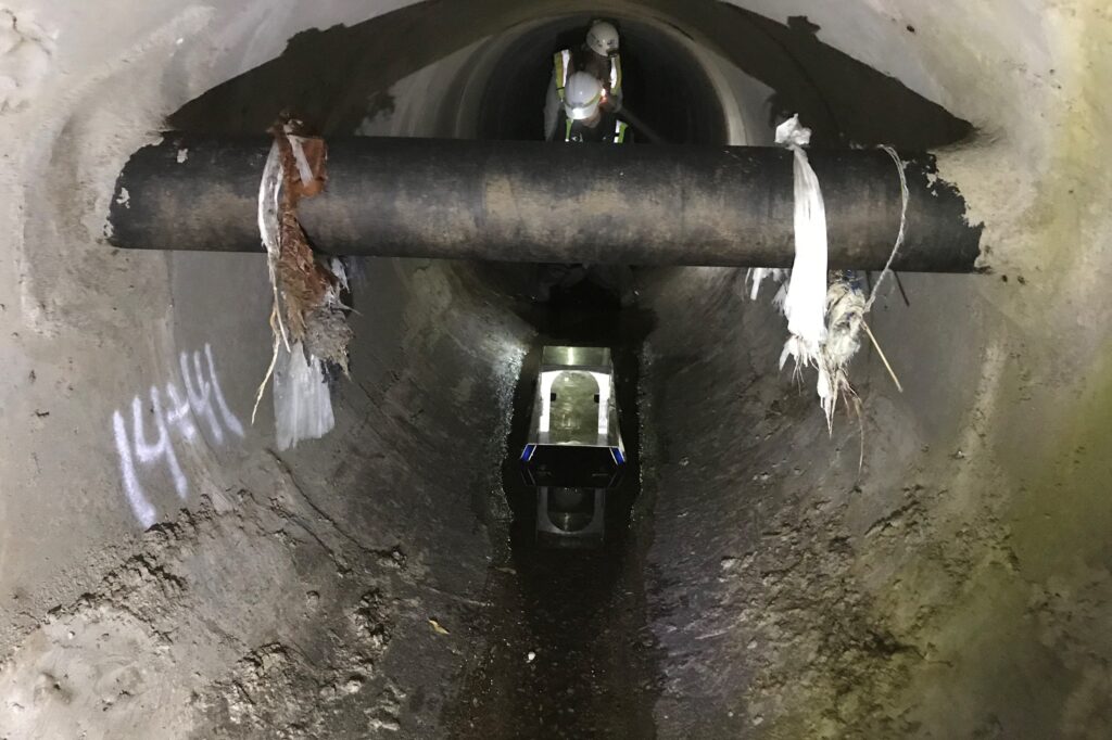
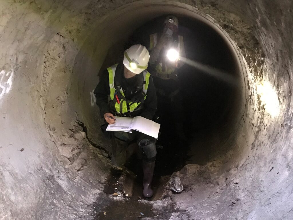
Dibble also proposed a concurrent manned entry for a visual structural inspection to assess the condition of the storm drain so the City could identify any needed maintenance or repairs. The team performed the investigation using both visual and non-destructive physical probing to determine the integrity of the existing concrete and documented any defects using digital photographs and video recording.
Each team member completed Occupational Safety and Health Administration (OSHA) compliance training for confined space entry. Our subconsultant, American Rescue Concepts (ARC), provided stand-by rescue and emergency extraction services while the Dibble team was working within the storm drain.
Plan of Action
While planning the manned entry, Dibble’s flood control practice evaluated possible sources of flow into the storm drain and determined the risk of flash flooding was minimal. The team that entered the storm drain was kept to a minimum to reduce safety hazards. ARC was on site daily to assist with any safety concerns and conduct a routine safety meeting prior to entering the storm drain. The team wore air quality monitors to ensure there was no exposure to harmful gases.
Survey
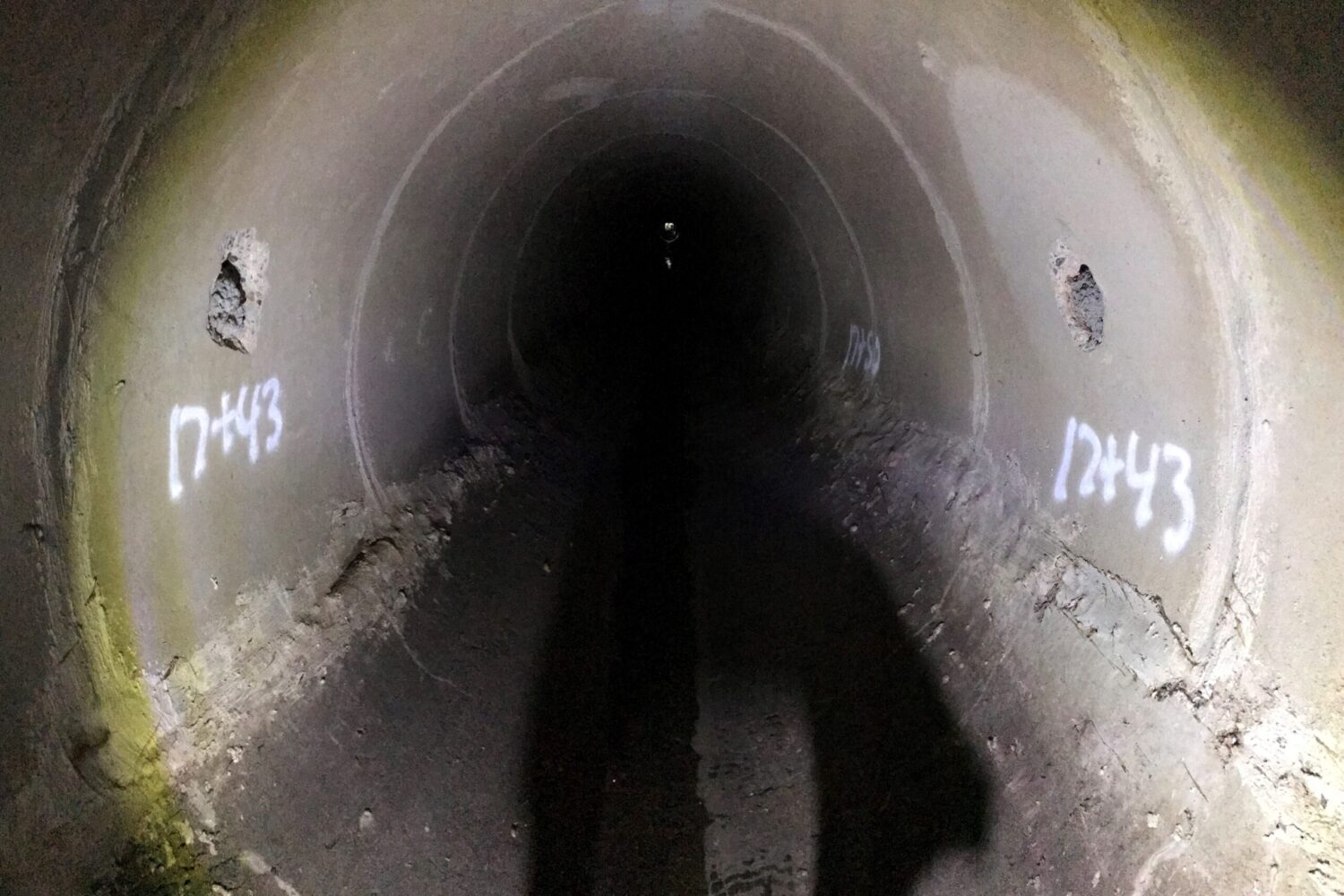
The team located manholes approximately every 500 to 600 feet along the unknown alignment of the storm drain. After brainstorming options for establishing survey control, the team took the northing, easting, and elevation of every manhole centerline and subtracted the known invert elevation of the manhole to establish the control coordinates for the survey.
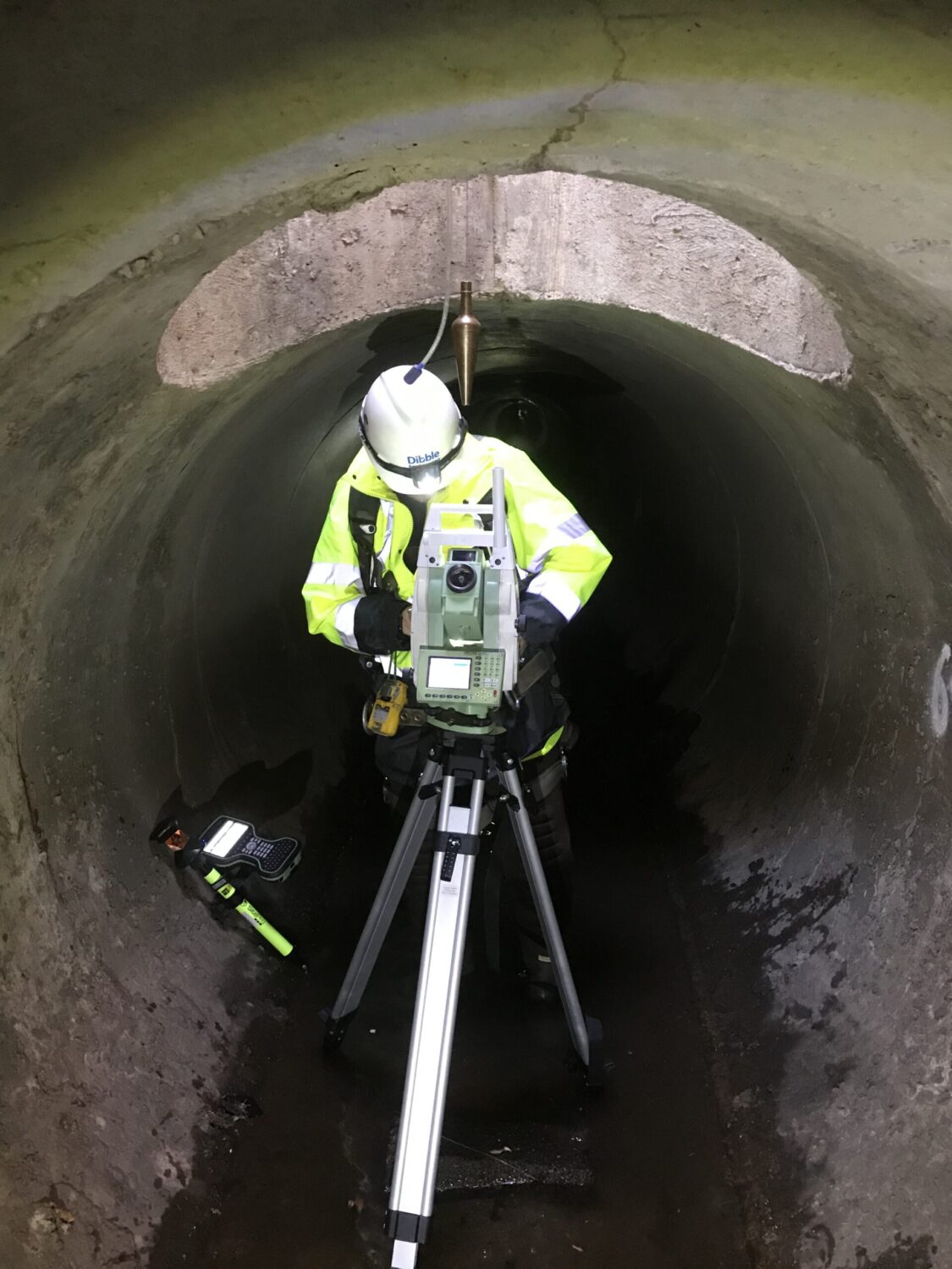
Once inside the storm drain, the robotic total station was set up and centered under a plumb bob, which was hung down from the ground-level manhole opening. This process was established at every manhole location to provide checkpoints within the survey to verify accuracy.
Using the robotic total station allowed only a single surveyor to be inside the storm drain. After establishing the positioning, the surveyor took distance and angle measurements using Bluetooth technology on the robotic total station.
Structural
During the manned entry, the structural team documented existing conditions of the storm drain and assigned the observed defects with deficiency rating similar to FHWA-NHI-16-039 and FHWA-NHI-130055 standards.
The team compiled defect location plans, which helped uncover why defects occurred at certain locations and provided recommendations and repair costs for improvement. The team also created interactive diagrams for integration into the City’s maintenance program.
Manned Entry Discoveries
The survey and structural teams discovered that while most the pipeline was straight, the pipeline varied greatly in direction at the Greenway Road intersection. The data obtained at this location added valuable details to the construction documentation.
The structural team did not discover significant deficiencies within the pipeline. The structural assessment documented the deficiencies and other observations for future rehabilitation or maintenance efforts.
Conclusion
Survey and condition assessment of a storm drain through manned entry is uncommon due to complexities of the confined space entry. After two grueling days immersed in the storm drain, Dibble completed survey and structural inspection of the storm drain. This unique survey method accurately located the storm drain on the construction documents for the 35th Avenue WTM replacement. The structural assessment confirmed the location and condition of the storm drain and will allow the City to integrate the documented deficiencies into their maintenance program.
Markets Mentioned
Water
Services Mentioned
Infrastructure Rehabilitation, Survey & GIS, Structural Engineering
This Case Study PDF
Project Manager

Project Details
Project
35th Avenue Storm Drain Investigation
Location
Phoenix, AZ
Market
Water
Owner
City of Phoenix
Engineer
Dibble
Delivery Method
Design-bid-build