Santiago Trail Water Treatment Facility
Executing a nitrate treatment facility and increasing water storage capacity to meet a community’s long-term needs.
Written by: Jake Nelson, PE | Susanna Mabery
Introduction
Located in southern Arizona, the City of Casa Grande is continuing to experience growth, both in its population and economically as new businesses move into the area. A key element to providing stability to a growing community is through a reliable and safe supply of drinking water.
In 2016 the Arizona Water Company (AWC) observed increasing concentrations of nitrates, which began approaching the Environmental Protection Agency’s (EPA) maximum concentration limits of 10 milligrams per liter (mg/L). Pinal County’s long-term agricultural focus contributed to the steady increase of nitrate concentrations in the geology and aquifer. When those concentrations were projected into the future, it was anticipated that nitrate concentrations could reach or exceed the federal limit of 10.0 mg/L by 2021.
AWC identified the need to greatly expand treatment capacity in this area, and to increase storage and distribution capacity, as well to plan for the long-term needs of the community. To do this they needed to create a nitrate removal facility (NRF) to treat the ground water and build a storage tank and booster pump station to meet the water needs.
Method
AWC initiated and completed the Santiago Trail Water Facility project, which was specifically planned and completed to meet the following primary goals:
- Maximize the use of two existing wells (3,000 gallons per minute (gpm) combined) and deliver water with a target nitrate concentration of 7 mg/L or less as nitrogen, when combined or used individually.
- Provide the ability to easily expand treatment capacity with a third well to 4,500 gpm in the future, which equates to 6.48 million gallons per day (MGD) of water treatment capacity.
- Provide storage capacity for 2 MG of water and the ability to provide an additional 2 MG of water storage in the future.
- Provide distribution capacity of 10.8 MGD of water with a booster pump station to improve the pressure and reliability in the water distribution system that extends through Pinal Valley water system.
- Add the ability to expand the distribution capacity to 10,500 gpm in the future, which equates to 15.12 MGD capacity.
- Improve the resiliency and reliability of the water distribution system and protect existing water mains in the community system.
Working together as a team, Fann Environmental (contractor) and Dibble/GHD Inc. (engineers) consulted with AWC to develop a complex and unique facility design that focused on proactive improvement and resiliency for an existing water production and distribution system. The project was completed using the design-build (DB) method.
Plan of Action
Water Quality Considerations
Three existing wells supply groundwater to the site, and each one has unique water quality parameters, including varying and seasonal concentrations of nitrate. GHD evaluated more than ten years of historical water quality data, using statistical analysis, in combination with hydrogeological considerations, for the current and long-term performance of each well. GHD developed a matrix of seven operating scenarios to capture all possibilities of both the hydraulics and water quality and completed mass balance evaluations to predict the performance across all current scenarios, and over a 20-year life cycle horizon. A summary of the operational scenarios evaluated are listed below.
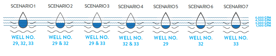
The result of these evaluations developed specific blending and treatment strategies, used both during design and operation of the NRF treatment systems, produce compliance in performance throughout the life cycle of the project.
NRF General Process Description
The team planned and designed the NRF to treat up to 3,000 gpm in the current condition and sized the facility to accommodate for future expansion, with a treatment capacity of 4,500 gpm. All design decisions considered what was needed to work in both current and future conditions; systems in the current condition would require no change or exchange, only the addition of components to meet the requirements for future conditions. This level of planned flexibility will result in significant capital savings in the future, while maintaining operations and maintenance (O&M) cost efficiency from day one of operations.
Ion Exchange System
The treatment system is designed to be operated as a blending system with 1850 gpm being treated by an ion exchange (IX) system. Blend/bypass flow to the NRF treatment system is controlled by a flow meter and flow control valve. Nitrate analyzers are provided on both the bypass line and treated water line for monitoring the performance of the system. Influent water is first filtered using two stainless steel pressure filter vessels, which each consist of 16, 5-micron bags, to remove suspended solids, and improve the performance of the ion exchange.
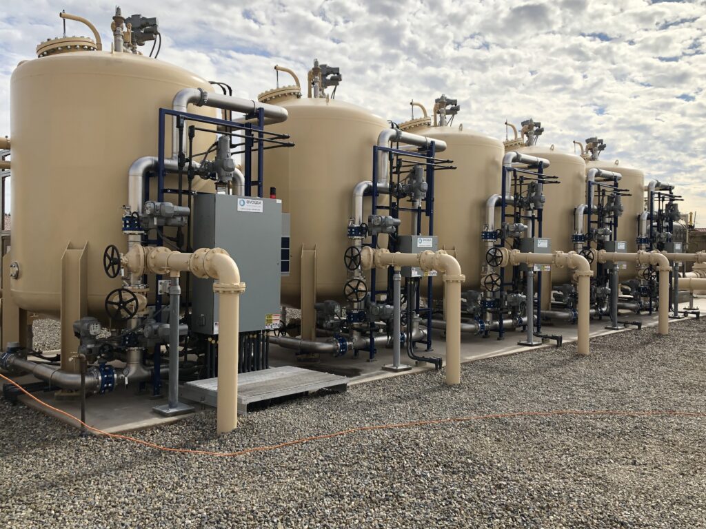
(IX) Treatment Technology
This system is provided in a one working/one standby configuration to ensure there are back-up measures in place. Additionally, the system has structures, piping, and appurtenances to accommodate a future, third pre-filter. Treated flow is conveyed from the stainless steel pressure vessels to five pressurized IX vessels for nitrate reduction. This system operates in a four working/one regeneration configuration so when one vessel goes through a regeneration cycle, the four other vessels maintain full capacity. Each IX vessel is filled with approximately 236 cubic feet of Purolite A520E resin for nitrate reduction and can accept two alternative IX medias. The ability to use an alternate IX media gives AWC flexibility for future media replacement by allowing them to bid multiple providers for the media, while maintaining cost certainty for long-term costs of O&M. In general, more than 75% of the total life cycle cost of water treatment systems can come from the long-term O&M costs, in comparison to approximately 25% of the total project cost spent on the initial capital investment. Therefore, a focus on the long-term flexibility and resilience of the system is the best way to promote a reduced life cycle cost.
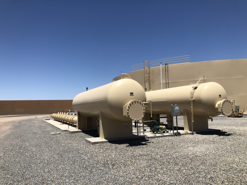
Brine Regeneration and Water Recovery System
The DB team planned and designed the system to promote a reduction in water loss by recovering approximately 99% of the raw water and maximizing the life of the IX media, both of which are significant long-term O&M costs to sustain the facility. Other support systems included in this facility to maintain the treatment capacity include a brine regeneration system and water recovery system. The brine tanks have been sized to accommodate an increase in treated water flow of 4,500 gpm in the future.
Post Treatment
After treatment and blending, the water is conveyed to the 2 MG water storage tank for disinfection and distribution. The facility was designed to accommodate future considerations for an additional water storage tank, including additional booster pump capacity.
Hydraulic resilience is key to the life cycle of a water treatment facility during the treatment, storage, and distribution phases. Flexibility and reliability in the system must be maintained during both typical and atypical operation.
Hydraulic Considerations
Common challenges of similar projects involve assumptions relating to static, average, or normal conditions. Our civil engineers anticipated the boundaries of the conditions. Our DB team, with input from AWC, identified that the existing transmission and distribution pipelines in the system experienced low and high pressures, along with the typical quantity of pipe failures/breaks. The DB team used an advanced transient analysis to predict the boundary conditions and all unwanted conditions the system currently experiences and developed alternatives to mediate those conditions.
The results of the transient analysis resulted in the selection of hydropneumatic tanks to mitigate low and high pressures and improve the overall distribution system resilience.
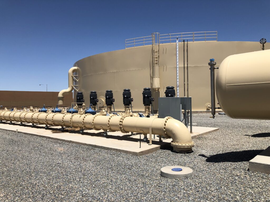
Booster Pump Station
The new booster pump station consists of six new booster pumps, each with the capacity to pump 1,500 gpm (2.16 MGD). The firm capacity of the pump station is 10.8 MGD. Space was provided for two future pumps, which would increase the firm capacity to 15.12 MGD. Two of the pumps are powered with variable frequency drives (VFD), enabling the pump motors to operate at higher or lower speeds, depending the water system. The VFD’s result in a higher overall operational efficiency, which translates to reduced power consumption and associated costs.
In conjunction with the VFD’s, the hydropneumatic tanks contribute to a higher pump station efficiency. They also function to protect the water system from damage due to transient pressure waves by acting as a cushion to dissipate the waves.
Storage Tank Design
Corrosion Protection
The storage tank is equipped with an automatic controlled impressed current cathodic protection system for corrosion protection. In addition to this system, the tank interior and exterior coatings meet AWC’s Storage Tank Coating Specifications. The exterior coatings are polyurethane based, and the interior coating are epoxy based, which both provide an extra corrosion protective element, and enhance the systems resilience to corrosive failure.
Venting
AWC requires larger vents on top of the storage tank to provide access to the dollar plate, which is a critical circular steel plate that provides structural support of the roof rafters. Larger vents help to decrease future maintenance costs and failure due to corrosion. AWC takes a proactive and advanced approach to the design of venting for storage tanks.
Proper design of an air vent should use multiple engineering techniques, including direction from AWWA manuals of practice and the Hydraulic Institute. Additionally, there are three separate systems that must be evaluated to determine the air flow requirements to support proper hydraulic operations, and ensure the vents are properly sized to accommodate all operational, maintenance, and emergency conditions such as:
• Tank fill system – A hydraulic analysis is required across the variety of operational scenarios to predict the minimum and maximum flows, fill rate, and head space. A series of engineering calculations are required to quantify the air flow requirements to exhaust air from the tank to support the filling.
• Tank draining system – The tank drains under two conditions including normal operations for distribution and to drain the tank for maintenance and inspection. Both require a hydraulic analysis to predict the minimum and maximum flows and drain rates. Then air flow requirements to introduce air to the tank are determined to support the draining activities.
• Tank overflow – This is the most critical analysis. Like the steps described above, the engineer must determine the maximum condition during tank overflow. Failure to provide adequate air into the tank during an overflow condition can partially air lock the overflow, limiting the capacity, and potentially leading to surcharging inside the tank.
Installation
The project was delivered via DB method, which streamlined communication, coordination, and the partnership amongst the team members. Together, the DB team members resolved the design issues internally, saving time and money for AWC. The project design decisions considered current and future operations, similar to the process used on the NRF. This level of planned flexibility will result in significant capital savings by maintaining O&M cost efficiency from day one of operations.
Immediate and Long-Term Resiliency
Redundancy and resilience were provided to protect existing infrastructure in the community, including pipelines and wells. Our team’s experience with not just design and construction, but also long-term operations, expansion, and maintenance, provided the insight to properly plan this project to meet both today’s and future needs. By reducing the life cycle cost of infrastructure, the team intentionally considered the holistic life of the project from inception to decommissioning.
Specific approaches the DB Team planned and designed included:
- Placing the largest power demand components (BPS), closest to the electrical gear, which reduced the quantity and length of the most expensive power and control conduit.
- Using symmetry to plan for future expansion, by using common pipelines, and providing future connections, thereby reducing future improvement costs, and minimizing the complexity in operations. This also allows for the future construction of the following key project components, with minimal site changes:
- Future 2 MG storage tank
- Future (3) NRF pressure vessels
- Future (1) NRF Brine Pump Skid
- Adding variable frequency drive (VFD) motors and hydropneumatic tanks to increase energy efficiency and reduce potential damage to existing water system piping infrastructure by mitigating impacts of transient pressure waves.
- Bypass piping so the storage tanks can be bypassed if needed during times of maintenance, utilizing isolation valves. Well No. 32 and 33 are routed through the NRF and chlorination for treatment and then routed through bypass piping straight to the BPS. Well No. 29 uses a similar approach following its arsenic removal and chlorination.
- The chlorination system installed post nitrate removal treatment features a double-walled tank for added protection against tank failure. Using the double-walled tank also allowed for a reduction in the concrete containment structure and reduced the expense; the extra layer on the tank provides the necessary level of chemical containment.
Cost Savings
To minimize long term effects on the project and maintain the contract schedule, the contractor, Fann Environmental, pre-ordered the steel needed for the project prior to the final release of the shop drawings. While this was a risk on the contractor’s behalf, with the price of steel on the rise, locking in the price early in the project was an innovative way to reduce the overall cost of the project.
Efficient site layout and footprint to minimize construction costs and optimize operational and maintenance capabilities, included investing capital at the time of the project, to promote the ease of facility expansion in the future.
Conclusion
The DB team, including the contractor, its engineers, and subcontractors, successfully delivered the facility “turnkey” to AWC, including all design, permitting, and construction necessary.
The NRF and BPS efficiently meet the current capacity, quality goals, and provide the ability to easily expand capacity in the future.
Blending of the treated water is adjustable, depending on changing nitrate concentrations, providing long-term reliability of the use of the nitrate treatment media.
The project resulted in a holistic, robust, and aesthetically pleasing site that blends into the surrounding community’s character, while providing sound infrastructure to meet existing water demands.

Markets Mentioned
Water+Wastewater
Services Mentioned
Water + Wastewater
This Case Study PDF
Project Manager

Project Details
Project
Santiago Trail Water Facility Project
Location
Casa Grande, AZ
Market
Water+Wastewater
Owner
Arizona Water Company
Engineer
Dibble/GHD
Contractor
Fann Environmental
Delivery Method
Design-Build
Awards
2020 ASCE Phoenix Branch “Large Project of the Year”