Maintaining the Energy Gradient Through Custom Sewer Structures
Written by: Crystal Faucett and Keith Faucett, PE
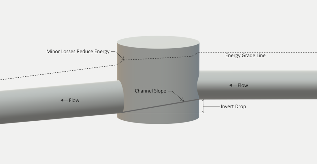
Dibble has been designing successful sewer solutions since 1962. While every sewer design is based on common principles, each has unique requirements, and small adjustments—such as the drop in elevation across a gravity sewer structure—can significantly affect system efficiency and longevity. This applies especially to custom sewer structure design. When wastewater flows through gravity sewer structures, some energy is lost due to changes along the flow path such as expansions, contractions, bends, and merging flows (minor losses). One way engineers account for these minor losses is by providing appropriate invert drop: the drop in elevation between the inside bottom of the incoming pipe and the inside bottom of the outgoing pipe. Engineering standards and best practices streamline this effort. For example, a common practice is to provide a 0.1-foot to 0.2-foot invert drop through gravity sewer structures, such as manholes. This concept is demonstrated in the published standards of many agencies, including the City of Phoenix, Pima County, EPCOR, and others. While this typical 0.1-foot to 0.2-foot drop is appropriate for most applications, larger structures may require additional invert drop to overcome head loss, maintain the energy gradient, and meet construction tolerances. To determine the appropriate invert drop, we calculate the minor losses in the structure as discussed below.
Review of Minor Loss Calculations
There are at least a couple of approaches for calculating minor losses. Each produces similar results and uses the Energy equation for head loss below:
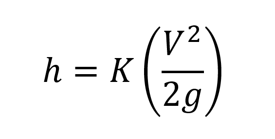
where
ℎ = minor head loss in feet due to bends, expansion, or contraction
K = loss coefficient (unitless). Using tables from literature (Brater, et al. 1996, p. 6.37; Crowe, Elger and Roberson 2005, p. 391), we can determine the K value for each type of loss including bend loss, expansion loss, and contraction loss.
V = flow velocity in the pipe in feet per second (ft/s).
g = gravitational acceleration constant (32.2 ft/s2).
To calculate the total minor head loss in a structure due to bends, expansion, and/or contraction, we compute the minor loss due to each condition (ℎ) using the equation above, then add the losses together.
Example: Calculating Minor Loss Due to Bend
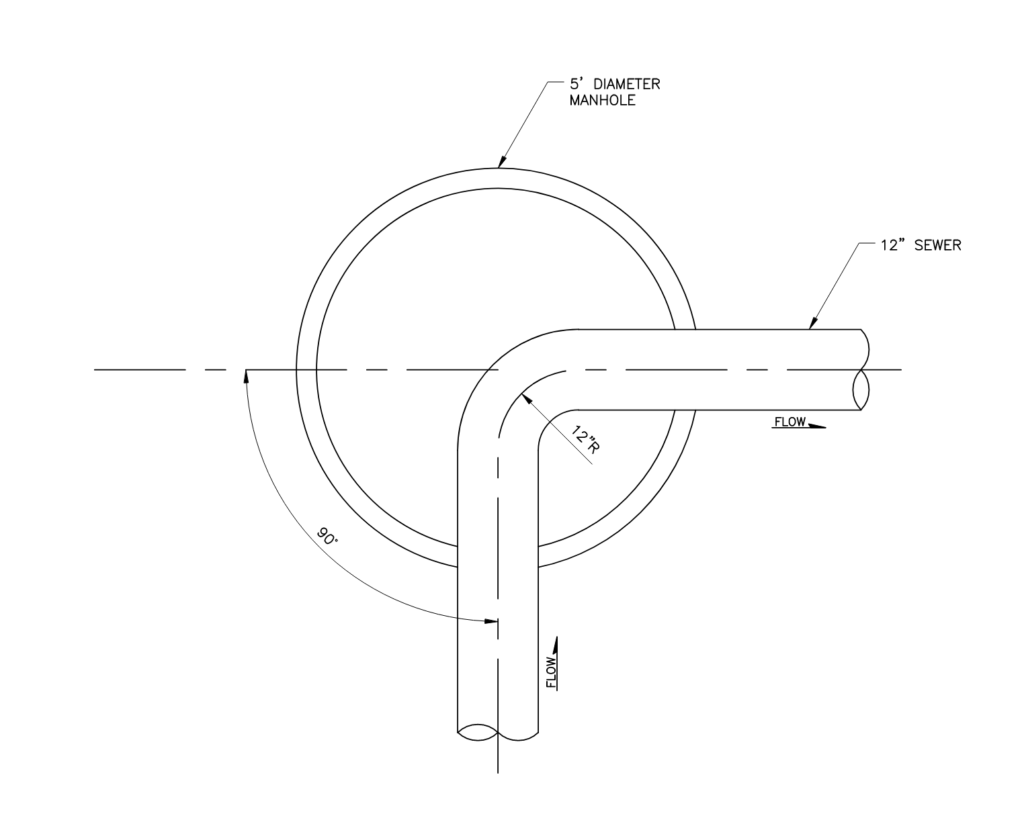
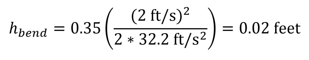
The example above shows a 12-inch sewer pipe bending 90 degrees within a manhole. The radius of the bend is 12 inches, therefore the bend radius to pipe diameter ratio (R/d) = 1. If this sewer is designed to maintain a velocity of 2 ft/s when flowing full, then the head loss due to the bend is 0.02 feet (calculation below). Therefore, the typical invert drop of 0.1 to 0.2 feet is more than enough to overcome the minor head loss in this structure.
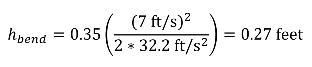
But consider the same pipe bend with a higher flow velocity of 7 ft/s (calculation below). In this scenario, the typical invert drop of 0.1 to 0.2 feet would not be sufficient to overcome the head loss of 0.27 feet. While a flow velocity of 7 ft/s is at the high end of acceptable, this example shows the importance of confirming whether the general practice is appropriate for a specific design.
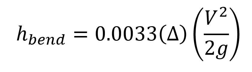
Another approach for calculating head loss due to a bend is to simulate an open channel storm drain. The Hydraulic Engineering Circular No. 22, Fourth Edition: Urban Drainage Design Manual (Atayee, et al. 2024, p.145), also known as the HEC 22 manual, also uses the energy equation, but provides an alternate method for determining the constant, K as shown below:
Consider All Sources of Head Loss
In large or custom sewer structures, there are often several minor losses involved. Consider if two 12-inch pipes enter a manhole and exit through an 18-inch pipe, as shown in the example below:
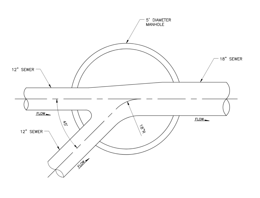
In this scenario, we have head loss due to a bend, an expansion, and a contraction. Again, we can use the Energy equation for head loss to calculate each of these losses, then add them together to determine the total minor head loss in the structure.
Another consideration is head loss due to merging flows. The Handbook of Hydraulics (Brater, et al. 1996, p. 6.44) recommends an iterative method to determine the losses due to the momentum of merging flows in a structure. The HEC 22 manual (Atayee, et al. 2024, p. 148 to 157) provides a non-iterative approach to determine these losses based on the angles of incoming pipes relative to the outlet. Both approaches consider the energy grade line across the structure.
Project Examples
Below are examples of large custom sewer structure projects in which we applied these concepts:
Tucson Boulevard Diversion Structure
Northwest Outfall Sewer Siphon
See also Designing Large Custom Sewer Structures.
For each project, Dibble carefully examines the overall purpose down to the small details, which helps ensure our designs operate as intended. This benefits owners and stakeholders and helps to protect public health.
Key Takeaways
- Typical invert drops of 0.1 to 0.2 feet may be insufficient for larger structures.
- Multiple sources of head loss—including bends, expansions, contractions, and merging flows—should be considered when calculating head loss in complex sewer designs.
- Real-world applications, as demonstrated in Dibble’s project examples, illustrate how theoretical principles translate into practical, effective solutions.
While our communities continue to evolve and grow, time-tested engineering principles remain constant. Standards and common practices streamline the design process but do not replace quality engineering and careful attention to detail. A thorough understanding of the engineering fundamentals is crucial for meeting infrastructure needs for generations to come.
References
Atayee, A.T., Herrman, G., and Kilgor, R. 2024. Hydraulic Engineering Circular No. 22, Third Edition: Urban Drainage Design Manual. Washington, D.C.: U.S. Federal Highway Administration.
Brater, Ernest F., Horace W. King, James E. Lindell, and C. Y. Wei. 1996. Handbook of Hydraulics. New York: McGraw-Hill.
Crowe, Clayton T., Donald F. Elger, and John A. Roberson. 2005. Engineering Fluid Mechanics. New York: John Wiley & Sons, Inc.
This Case Study PDF